|
|
|
Now that the FireFly's hangar is less than five minutes away from my home, it has become much easier to spend a few minutes working on it and not shoot the whole day. I have not been able to achieve the fuel flow rates that are posted by Simonini, although I have been coming closer to those posted by engine importer, Speedwing. As over one hundred hours have accumulated on the engine, several things have become apparent. First I have had to increase the number of turns open on the idle air screw. And second, when I have run the engine on two flights on the same day and at the same cruise rpm, the fuel flow rate could vary as much as a 0.3 gph. Also, in the 5,600 rpm and above, the EGT's were very peaky, and so I have cruised at whatever rpm at which the EGT would not exceed 1,250 degrees F. At first I felt that the fuel pump may be failing and it could not supply enough fuel at the higher rpms. But the spark plugs said rich. |
 I started leaning out the engine by dropping the needle one quarter a slot at a time (shims). Fuel flow rates dropped from 2.5+ to around 2.2 gph. As this happened, the rpm at which the EGT started to exceed 1,250 degrees F came down to 5,200 rpm, and the fuel flow variation remained from flight to flight. I thought that may be the throttle cylinder and needle may be vibrating up and down in the upper rpm range. Checking the throttle cylinder, I found wear marks that indicated the cylinder was vibrating. Vibration causes the needle to dance in the jet. The only way to reduce this vibration was to increase the return spring force.
|
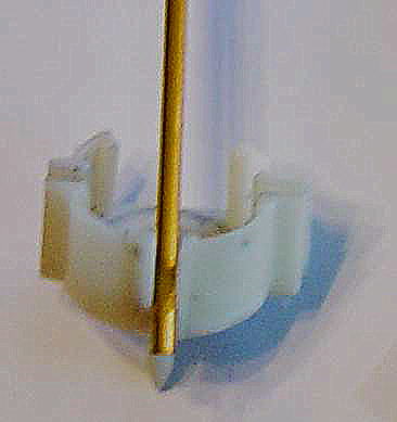
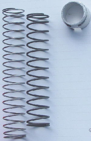 To check this out I made spring compressor insert that would increase return spring force. It is shown on the upper right. After installing it, the fuel flow rate fell to 2.13 gph. I called Bing and purchased the strongest return spring. After installing this spring, fuel flow rates were very consistent within 0.05 gph. Dropping the needle continued until the clip was in the next to top slot. The fuel flow rate came down to 2.07 gph.
The original medium return spring is shown on the left and the heavy return spring is on the right. After installing this spring, the engine was running so rich at idle that if one completely closed the throttle on final approach, the engine would quit. The 30 idle jet in the Bing was the smallest idle jet listed by any vendor. I called Bing and found out a smaller 25 idle jet was available. With this jet, the engine idled well with the air screw at two turns out. EGT increased in the lower non-flight rpm range and this helps reduce engine warm up time. EGT reads 1,000 degrees F at 3,000 rpm. But the rpm at which the EGT first reached 1,250 degrees F dropped to 5,000 rpm. At this point I had a dilemma in that I could cruise at 5,000 rpm at improved fuel burn rates, and take off and climb out at 6,400 rpm with the throttle wide open to take advantage of the main jet. But I could not use the engine in the 5,000 to 6,000 rpm range. |
 Next I looked at the needle and needle jet configurations. The Bing chart for the 11H2 needle shows that the taper does not start until the slide moves to the 34% open position. Since the Victor 1+ will run at full power at 30%, this indicated that the engine was running completely off the idle jet and the throttle slide cut off. To check this out, I placed the throttle in the closed position, removed the carburetor float bowl, the mixing chamber, and the needle jet. At this point the needle can be seen hanging down from where the mixing chamber screwed in. The needle-exposed distance up to the machined surface was measured. Then the mixing chamber and needle jet was replaced and the distance from the machined surface down to the bottom of the mixing chamber was measured. Next the needle, needle jet, and mixing chamber were removed and taken home to obtain additional measurements.
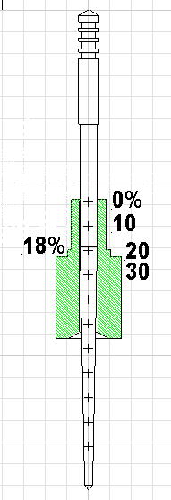
After taking the measurements and by using CAD software, the needle and needle jet were reconstructed in their relative throttle closed positions. What was found is displayed to the left. The taper starts at the 18% throttle open position. Typically the Victor is turning 5,000 rpm at about 16%, so this indicates that the length of the needle straight section in the jet is regulating the needle and jet fuel flow. I decided to modify the needle. First I relieved the needle starting at the 30% open point and up by making a straight cylinder from 30% to 40% with an OD of 0.0755 inches. A flight test with this modification showed that engine speed could be reduced on the main jet from 6,400 rpm to 6,000 rpm before the EGT would approach the upper limit. Then I removed material from 5% to 25%. Trying to introduce some taper through the 5% to 20% region. Additional test flights found that the EGT remained constant 1,200 degrees F from 4,000 to 6,000 rpm. Fuel burn rate at 5,500 rpm was 2.20 gph. Plugs indicate the engine was running a little rich. |
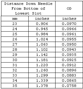 I mapped the needle and the data are shown on the left.
I need to run additional leaning out tests. I have purchased two smaller needle jets in an effort to boost EGT in the lower rpm range. But Winter is here and so it will be slow going. I removed the dribble bib from the carburetor inlet. With the 25 idle jet and the stronger throttle return spring, the bib no longer seems to be required. |
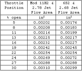 Looking at the Bing needle chart, the 6S2 needle looked like the best ready made needle that would match the modified 11H2. A 6S2 needle was purchased and mapped. For various throttle settings, the fuel flow cross sectional area between needle and jet was calculated for the modified needle. This same process was applied to the 6S2 needle except the needle jet size was lowered until the majority of areas in the upper power band made a good match.
As can be seen for throttle openings from 16% through 27% match well. The settings 13% and below show lower (leaner) cross sectional areas for fuel flow. This may be an improvement as the modified needle was showing a rich tendency in this region. The 6S2 needle and 2.68 needle jet were installed. After three flights, I consider the needle to be a good match for the FireFly, engine, and IVO propeller combination. The needle clip was in the bottom slot. In the below flight rpm region, EGT reading were higher than before. This promotes faster engine warm ups and reduces non-flight fuel waste. In the 4,000 to 6,400 rpm range, the EGT were flat. It is winter, and so running with the clip in the bottom slot may be ok, but it may be prudent to change from a 2.68 to a 2.70 needle jet and to lower the needle. The EGT were running toward the higher limit, but if the nose was pushed down and to lighten engine load, they do not show an increase. This would indicate that the engine is running toward the rich side. The plugs looked good. |
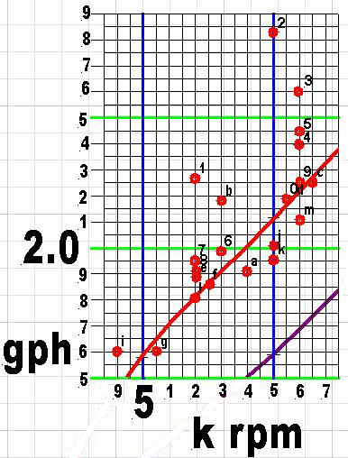
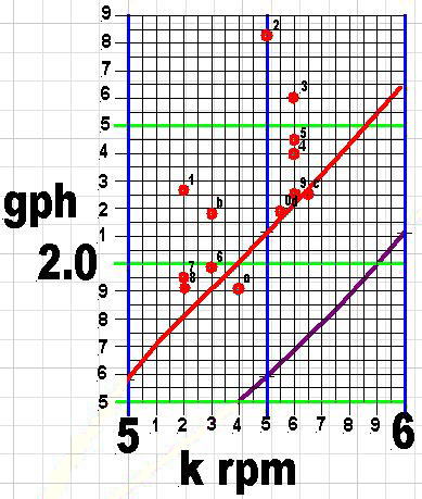 To the left is an abbreviated fuel flow chart. The engine distributor's declaration of engine fuel flow is shown in red. The purple line represents the engine manufacturer�s data. The red circles represent data obtained by flying FF004. These data points have been complied over the last four months.
The process started with taking a fuel reading in the hangar. Minimum engine warm up was two minutes, which also included taxiing to the runway. During cold weather the warm-up would exceed two minutes to enable coolant temperature to reach 130 degrees F. Climb to 500 feet agl was made at 6,400 rpm and then the throttle was reduced to the desired test rpm. Then a cruise/thermal climb was made to 1,500 feet agl and a similar flight pattern was flown to enable a thirty-minute or more flight. After landing and taxi back to the hangar, the FireFly was pulled back into the hangar and placed in the exact position it started from and a final tank reading was taken. Each data point was calculated based on the fuel difference and the ground to ground flight time. Before each flight, one spark plug was checked to be sure that the engine was not running too lean on the previous flight.
|
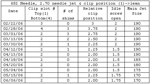 This table lists the carburetor jet and needle position changes that have been made. Main jet size was reduced until the EGT did not take a dip at or above 6,000 rpm.
At two turns, the idle air screw was too lean and the engine would quit after cruise throttle closure. Reducing the number of turns to 1.5 made the idle mixture too rich and dropped the EGT 50 to 75 degrees. 1.75 turns on the idle air screw seems to be the best compromise, and keeps the EGT flat over the 4,000 to 6,000 rpm region. The needle clip positions are listed in quarter of a slot. The Bing is too large and the Victor 1+ will top out at 6,400 rpm at a little over 30% open throttle. Such a small useable throttle range causes too large a change when moving the clip from one slot to another. To regain needle slot/clip adjustment sensitivity, shims were used to provide the finer one quarter slot positions. The engine was leaned out by dropping the needle one quarter of a slot on each flight until fuel consumption approached the red line. Then additional flights were flown at different cruise rpm to obtain new data points. At this time all of the latest points lie on or near the red line, and I see no need to take additional data points. I see no hope of reaching the manufacturer's curve. But I am very happy to be able to fly 50 to 55 mph at two gph or less. |
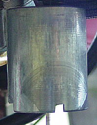
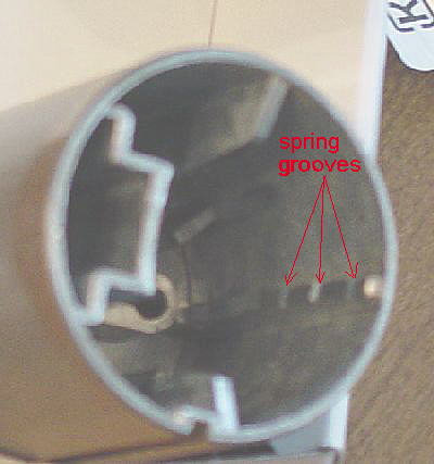
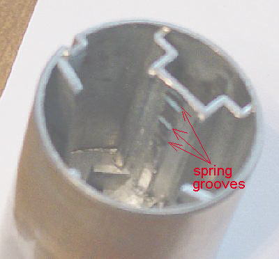 The strongest Bing throttle slide return spring has been in use for the last 25 hours. At low throttle settings, engine rpm had become unstable. Upon disassembly it was discovered that the spring had been flipping back and forth inside the pot metal throttle slide. As can be seen, the banging up against the boss on the inlet side of the throttle slide has worn grooves into the boss.
|
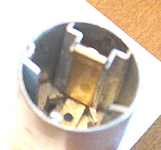
 The same was true for the opposite spline in that, the spring had actually worn grooves and had pounded the metal to the point that the spring cup could not be removed with out deburring the spline. Spline wear was much greater than boss wear because a narrower surface had to withstand the beating.
I elected to repair the slide, as a replacement slide would last another 25 hours before the next would have to be ordered. To replace the strong spring with the original spring would be moving back to fuel flow unstability. |
 A 1/8 x 1/8 inch brass "U" channel insert was installed over the spline. A file was used to remove material from the corresponding spring cup slot.
Brass is a good bearing material and it has a much higher yield strength than pot metal. So hopefully the brass surface will wear much longer than 25 hours. |
 A Dremel tool was used to remove what was left of the boss on the inlet side of the slide. A 0.016 inch thick piece of brass shim stock was cut 0.410 inches wide so that it would fit in between the small bosses on each side. The lower lip of the shim falls below the position of the spring cup. The upper surface was bent over the top of the slide. The brass shim is held in place with JB Weld.
|
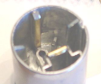 The brass channel was placed over the original spline. JB Weld was used to hold it in place. The channel was pulled out a little at the top to reduce the clearance between the new spline surface and the spring and there by reduce spring impact on the brass surfaces.
A test flight indicates the repair was effective. Throttle response was smooth and the low speed surging has disappeared. Now I have to wait and see if the repaired throttle slide holds up better than before. My apologies for the poor photo quality. |
 From July through December, 2006, I added a few more data points. It would be interesting to plot cruise speed against rpm on the same graph as fuel burn. When warm weather gets here, I will use the gps and voice recorder to take the data.
Further fuel economy gain was found by adding an air-fuel mixture control to the Bing. |