|
|
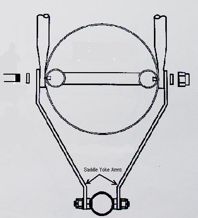 After removing all play from the stick and universal joint up at and under the seat and bolting the push rod bearings directly to the aileron control arms, a little lateral stick play was noticed in flight when the stick was in or close to the neutral position. The reason is due to too much clearance between the top and bottom saddle arm holes and the bolts or shim tubes. This allows the saddle to shift or swing back and forth a little on the bottom in reaction to sideways stick movement.
During flight at altitude and under low wind conditions, this play is not a problem. But when taking off and landing in a gusty cross wind, it reduces or delays the expected stick pressure response. This in turn delays the pilot's corrective action, and the FireFly wants to get a little bit a head of you.
|
|
|
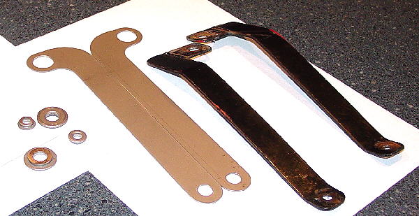
New arms were blanked out. Since there is a lot of shaking going on down in this area, the blanks were drilled and reamed with larger holes so that larger surface or wear area bearings with could be used. Flanged Oilite bearings of 5/8 & 3/8 inch OD were purchased and cut to length. To save weight I had previously trimmed the through bolt. To be able to accommodate flange thicknesses, the arms were cut from thinner material. If I had not trimmed the through bolt, I could have re-drilled and reamed the original arm holes. |
|
|
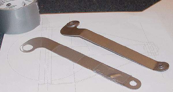
To protect the surface while bending, two layers of duct tape were wrapped at the bend line. The arm was placed in a vice at the bend line. A wood block was placed on top of the vice and against the exposed surface. By tapping the wood block free end with a hammer the arm was slowly bent. To check progress, the arm was removed from the vice and placed over a template drawing. The process was repeated until there was a match. |
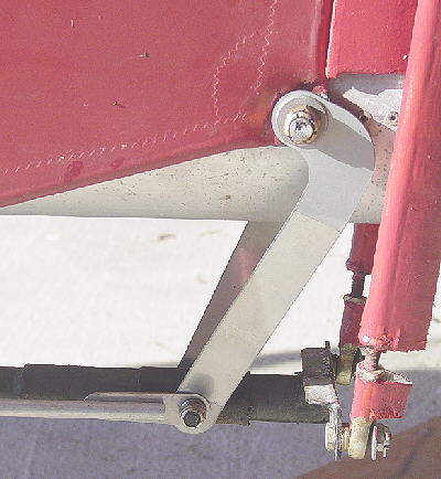 The new yoke arms mounted on the FireFly. The flaperon control link hole was enlarged to 3/8 inch ID. There is much less wobble in the assembly as the stick is moved from side to side.
Because thinner material was used, there was a net weight savings of 1.8 ounces. I could have saved a little more weight by making them straight.
|
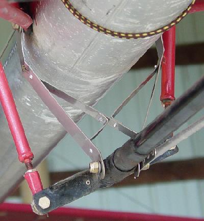 Although the new arms and shoulder bearings removed a lot of play and improved neutral stick pressure sensitivity, the bottom of the yoke continued to swing back and forth when the stick was displaced from the neutral position. To stop this swing and to further increase neutral stick pressure sensitivity, a triangular truss was placed in between the two links. This addition stabilizes each arm so they move as a unit and stopped all swing at the bottom of the yoke.
The cross configuration was drawn up on CAD and the outside shape was cut out and used to gauge if everything would fit. It took a couple of tries to get it right. Then a half-inch wide strip of stainless was cut to length and bent into the correct shapes based on the last CAD drawing. The two short pieces were drilled to accept 3/32 rivets. The corresponding holes were drilled in the long piece and the "X" was riveted together. This assembly was taken to the hangar and fitted to the yoke arms. Care was taken to pull the arms in tight from side to side and to keep equal aileron push rod spacing on each side of the tail boom tube with the stick is in neutral position. The top of the "X" was positioned low enough so that the truss does not interfere with flaperon full down position. One flight test with a gusty cross wind take-off and landing was enough to prove that the modification increased stick roll sensitivity about the neutral point. This change should make mid-day flights through unstable air more enjoyable and require less of the pilot's energy. |