|
|
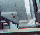
 The Victor 1 has dual ignition so one would like to test each ignition system separately to be sure that they are both working. I mounted two little momentary push button switches (Radio Shack) on the flywheel cover just below the ignition modules.
|
|
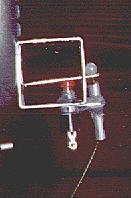
A second switch was placed in a hole drilled through a supporting web just back of the flywheel. This location was picked so that the switch would be protected from rain, and it is out of the normal view. It is a small double throw double pole switch (Radio Shack). This lets both mags be grounded with one switch, and its primary purpose is to preserve safety of others. If someone hand props the engine, or if someone removes the starter safety and manages to engage the electric starter, the engine cannot start.
|
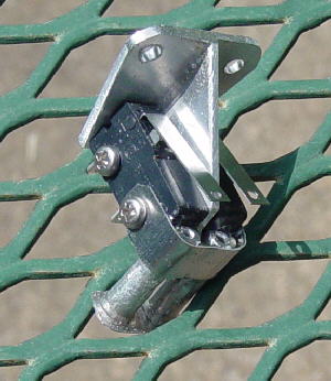 After flying with the above magneto kill switches for 29 hours, one failed, and I could not stop the engine. The whole assembly was modified to incorporate a more rugged switch and one with a higher electrical rating. The two lever snap switches were purchased from Radio Shack.
The switches were mounted on each side of a piece of "T" shaped aluminum extrusion. The activation guides were removed from the original switch assembly. A thin aluminum band was made to hole the guides in place and the inter space was filled with epoxy. The bottom ends of the guides were stabilized with another piece of thin aluminum and held in place with epoxy. Holes were drilled through the end of the lever arms to receive the woven fish activation lines from the cockpit console. |
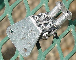
The bottom side, shows the electrical terminals and the sockets for the fish line guide tubes. The normally closed solder tabs were removed. The nuts were safetied with epoxy. Engine mounting hole spacing was maintained so that the assembly is a direct replacement. Placing the magneto kill switches on the engine has eliminated the engine noise problem with the radio. |
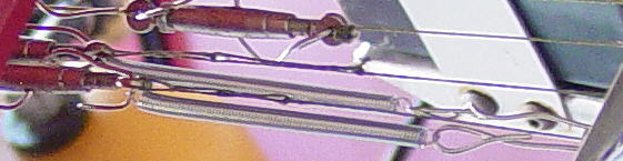
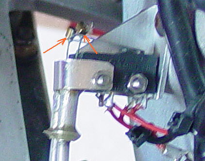 During very cold weather, I discovered the kill switch lever arms (red arrows in photo) did not have enough pull back strength to return the cockpit activation levers to the "open" / "off" / "run" position. I could start the engine, but up on testing I found one or the other of magnetos would be shorted to ground.
Part of the pull back problem was caused by friction between the fish line and the aluminum guide tubes. And another reason was that I installed some little turn buckles for easiy adjustment. These added some additional weight and increased the return force requirement. Small extension springs were slipped on to the turn buckle safety wires. The other end of the spring was stretched and safety wired to the control line mounting bar found on the lower left front of the engine mounting plate. With this arrangement the micro switch lever arms must only return about a foot of fish line through the guide tube from the switch to the engine mounting plate. A photo of this set up can be seen below. |
|
 I believe in using ready made as much as possible, but in this case it has not worked out well. It is very important for low weight and for low radio noise to mount the magneto kill switches as close to the engine as possible. The little "Cherry" pop action switches were very light but do not have enough return force and so helper springs had to be used to unload the plungers.
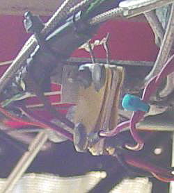
After trying several configurations while using these switches, I abandon them and manufactured my own switch. I used some fiber glass rod, two large safety pins, an aluminum extrusion, some brass shim stock, flat plastic from an oil bottle, and some JB Weld. These safety pins have enough spring force so that helper springs are not required. The mechanism is light weight, simple, rugged and will withstand abuse. |
|
Two pop revits hold the switch assembly to the control arm (black) mounted on the lower left front of the engine mount. To activate the switches, woven fish line is tied to the upper long leg of the pin and the opposite end is tied to an activation lever in the cockpit. When the lever is pulled the right leg of the pin is pull to the left and it grounds on control arm (black). To complete the circuit, the magneto ground wires were soldered to the brass tabs. This switch assembly was installed on October 24, 2007. |
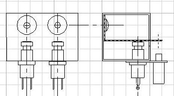
 The switches are activated by pulling on a woven fish line. A bead is tied on to one end and the line is threaded through a hole in the end of the cantilever spring beam just above the push button. The line is fed down through a stop and guide. The stop prevents one from exerting too much force and breaking the push button or bending the cantilever beam. The other end of the fish line will terminate at the left side of the cockpit. By placing the switches on the engine, one does not run the ignition grounding wire and its associated electrical noise down to the cockpit area. Hopefully this will reduce noise in my radio. Also fish line is much lighter than wire.
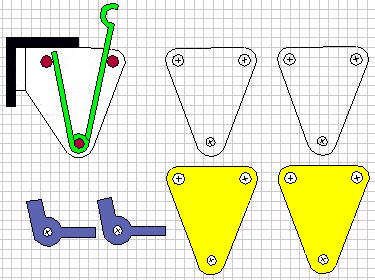 To the left is a modified CAD drawing to show the full sized individual parts. The outline of the aluminum "Tee" extrusion is shown with one of the modified safety pins (green) in place. The pin pivots on and is constrained by three 0.125 inch OD fiber glass rods (red) that were cut one-half an inch long. These rods pass through holes in the aluminum to hold another safety pin on the opposite side. Since the pins are the conductors, they must be insulated from the aluminum holder. Pieces of yellow plastic cut from a Penzoil oil bottle were shaped and drilled to slide over the same rods. One piece was placed on each side of aluminum extrusion to prevent the pins from touching the aluminum. Next the pins were put into place and then a piece of shaped brass shim stock (blue) was slid onto the lower pin. The wider tab was crimped to accommodate the short leg of the pin and the opposite leg was used as a wire attachment point. Next, another plastic insulator was slid over the rods so that the pin could not slide off the rod and to constrain the pin into the desired operational plane. To keep the whole thing together, JB Weld was dabbed onto the out end of the rods.