|
|
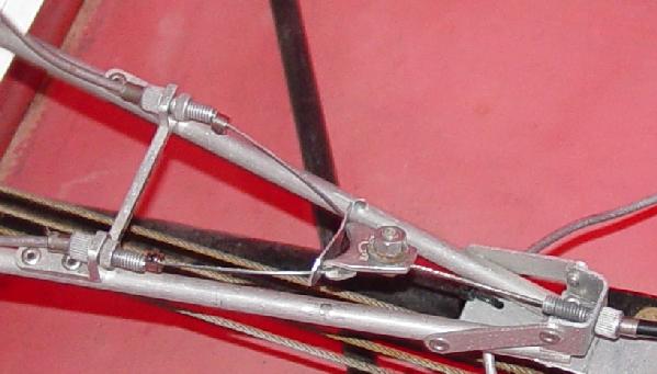
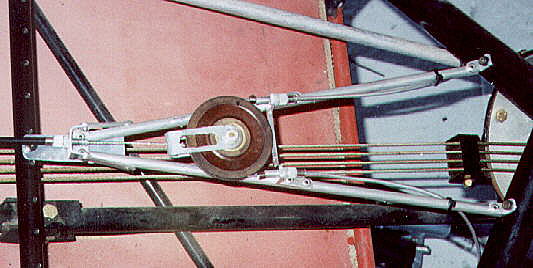 The brake cable feeds around a mixer pulley and then back down the second reaction tube and on to the second brake assembly. To prevent one brake from dragging due to one compression spring being stronger than the other, cable stops are used in the mixer to limit the amount of cable back travel. They can be seen on the cable just to the right of the pulley. Squeezing the brake handle on the stick retracts the cable on the left which exerts force on the pulley yoke. Brake lining wear can be compensated by screwing out the adjusters through which each cable passes into the mixer.
|
|
 |
|
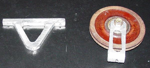
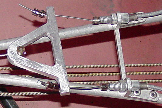 Replaced the splitter with a lighter (weighs one ounce less) piece of aluminum. This change lets one use shorter shifter cables and using the plug end. The shifter cable is threaded through the band, the brake reaction plate guide, through the reaction tubes up to the mixer, and through the hole in the outer wing of the splitter. Cable stops are used to keep the cables from returning too far and cable stops are used on the front side of the splitter to transfer the force from the splitter to the brake band. With this change, all adjustments are made inside the cockpit behind and under the seat. |
|
|
|