|
|
 A piece of one half inch wide leather strap was cut to that it completely wrapped the outside of the brake drum. An one half inch wide .025 thick aluminum band was cut and trimmed in length to fit over the leather. The aluminum band was rolled over circular form until it naturally formed a circle that was about a half inch larger in diameter than the outside of the leather strap circumference while it is on the drum. This was done so the brake band assembly will naturally spring away from the drum. The inside of the aluminum band was roughed with sand paper, cleaned, and then coated with JB Weld adhesive.
Next the leather strap was inserted into position and the whole assembly placed on the brake drum. A large hose clamp was placed over the outside and tightened down to squeeze the excess glue from in-between the band and the leather strap. After the adhesive sets, the band is removed. Next the bands are placed in the dish washer and run through several wash cycles to leech oil from the leather. After the bands are dry, one half inch was cut from one end of the band. Then each end of the band was bent out radially to form a tab about one half an inch high. One end is drilled so that the brake cable can pass through and the other end so than the reaction tubing bushing can pass through.
|
 The leather lined brake bands held up well, but I could not get all of the oil out of the leather so the coefficient of friction was lower than expected. My right hand on the stick would tire of squeezing the brake lever on the way to the runway.
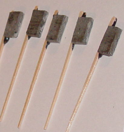
I searched and found a high coefficient clutch material offered by McMasters. I purchased a sheet and cut a long strip 1/2 inch wide, and then cut this strip crosswise into pieces about 1/4 of and inch wide. To the side of each of these little pieces I glued a tooth pick as a spacer. After the JBWeld KWIK adhesive had set, the tooth pick ends were cut off, and all excess adhesive was removed from the back (bonding) side so that the piece would lie flat on the band.
|
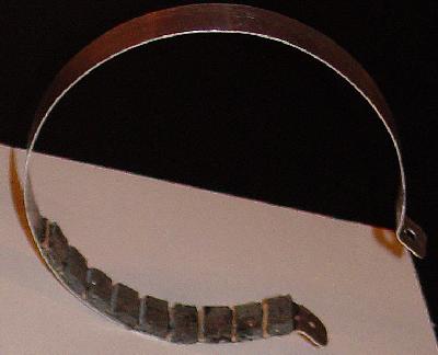 The band was carefully bent to shape so that it was just larger than the it would be if it was clamping the brake material onto the drum. Next the bonding surface was scored with a oval shaped file followed by cleaning with MEK to remove all oil from the surface.
Small portions of JBWeld KWIK were mixed, applied to the individual brake pad. Then the pad was placed into position and pressed onto the band to expel all excess adhesive. This process was repeated until all the adhesive was used up, and then another batch of adhesive was mixed and the process continued. The tooth picks act as spacers so that the band can flex in-between each pad, and this reduces band activation force. After all the pads have been attached, the band is placed in an oven. The assembly is baked at 250 degrees F for over an hour to cure out the adhesive. The band friction coefficient is much higher, and so brake activation pressures are reduced and band life improved. |
|
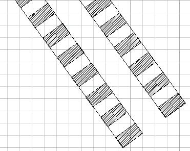
I increased the spacing between friction material blocks to save some weight and because the material has shown little wear.
|
|
|
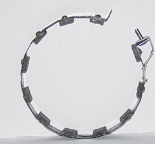
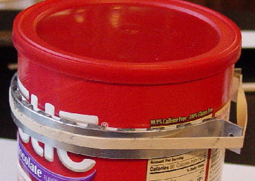 Next the assembly is placed over a can and secured into place with a rubber band/s. Then the whole works is put in the kitchen oven to cure out the JB Weld.
|
 The band is removed from the can, and the paper template torn and scrapped from the friction material. One does not have to worry about getting all the white glue off because initial burn in of the brakes will take care of it.
This method of making bands is much easier and quicker that what I have done before. One must rough and clean the inside surface of the metal band to ensure good bonding between the metal and the friction material. One additional tip, when cutting out the bands do not use a free sheared edge on the band. You have to cut the other side with a tin snip, and it will stretch the edge so that the band will curl and not lay flat when it is bent into shape. If one uses the tin snips on both sides, both sides will be stretch the same amount and it is much easier to bend the band into its final shape. |
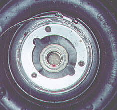
 The previous band design had no provision to keep the bands in place on the drum. The bands were suspended by the free legs above the drum. The idea was that the band would hang straight down over and surrounding the drum. The only thing that kept the bottom of the band from sliding off the drum was weight and the small amount of retraction clearance allowed by cable return stops located in the cockpit. As the lining and drum wear, more clearance develops and the danger of a band sliding off a drum increases so the clearance must be closely monitored.
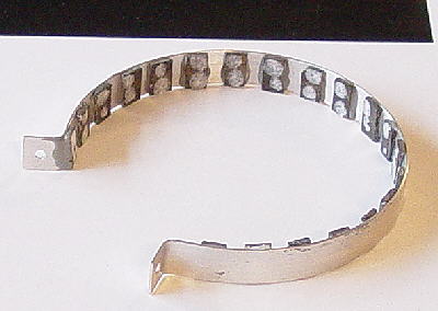
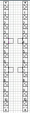
I did not monitor band clearance well, and so when I landed on tall grass field the grass pushed one of the bands off the drum toward the wheel. On roll out it tore the band to pieces. Since I had lost all the brake friction material, I decided to redesign the band with tabs to prevent the band from being forced into the wheel. During the redesign I increased the friction pad size to reduce the number of pads required (20 to 11 pads), and I made the band out of thin stainless steel. Full sized templates were printed, the back side sprayed with adhesive and wall papered onto the stainless steel. The bands were cut to shape with tin snips. Next the pads were glued to the back side underneath each cross hatched area using JB Weld. After the adhesive had set, all extra adhesive was removed. |
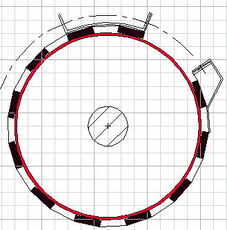 In this design the band was bent first. Bending was done by hand starting at one end and working toward the opposite end. As each bend was made the band was removed from the vice and placed over a full scale drawing of the assembly. The bends were adjusted until the band made a polygon that is just a little larger than shown in the drawing. Then the pads were glued into place.
After the band has been shaped, the tabs are bent 90 degrees. These bands have been mounted and seem to be working very well. They are simpler to make, require fewer parts to be made, and for some reason even with tighter release clearances, do not make any noise when released and require less handle pressure to activate. |
|
The design was good but the material was not. The fatique life of thin stainless steel was too short. Currently the bands are made from 1/2 inch wide steel strapping that is used to bind materials to pallets. A new problem developed. I did not have any problem keeping the friction material glued to the aluminum bands with JB Weld, but when I changed to the steel band, the pads kept popping off the band.
A Dremel tool was used to remove the excess screw length and to remove the first two screw heads where the band passes under the attachment point. |
 I recycled the friction material. The way I had previously attached the friction material to the bands was fairly tedious, and so I looked for a better way. I drew up some templates and cut them out. A couple of tiny white glue dots was placed on each hatched area. Then the friction pieces were positioned on the template and the glue allowed to dry.
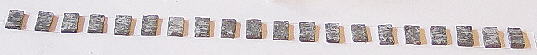 After the white glue was dry, JB Weld was applied to the upper exposed surfaces. Then the whole template and friction material assembly was curled into a circle on edge. The band was placed over the circle and the assembly pressed against the inside of the band to remove the excess JB Weld.
 To overcome the popping off problem, holes were drilled and tapped to 4-40 thread through the band and the pads. A brass screw whose threads were coated with JB Weld was used to clamp the pad to the band and to improve pad to band shear load capability.