|
|
|
The indicator is mounted on the bottom center of the instrument panel and directly over the rudder cables. Screws attaching two adjacent instruments were used to mount the indicator to the panel face.
|
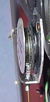 To activate the indicator, woven fish line is attached to one of the stick elevator control horns, threaded through a guide located in-between the rudder cables and on the floor boards. Next the fish line passes up through the guide on the indicator, is wrapped over the one inch OD behind the indicator dial, as shown on the left. Then the fish line passes back the way it came to the other elevator control horn. A small extension spring is used to maintain tension in the fish line.
The indicator is not directly attached to the elevator, so it really indicates fore and aft stick position. This is not truly a direct measure of elevator position due to cable tension and droop, and in-flight elevator load. The indicator dial is scaled to reflect elevator angle changes. For testing purposes, what is of interest here is not absolute elevator position but the change in elevator position.
|
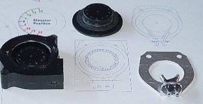 The indicator is made from a very small squirrel cage fan and motor. The housing and blades were removed from the fan. This provided a small hub about the outside of the motor that has a one inch outside diameter, and it is mounted on low friction ball bearings.
A back mounting plate was fabricated out of aluminum so that the modified fan and motor, and guides for the activating line could be mounted (JB Weld).
|
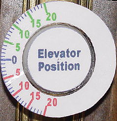 The scale was laid out so that full forward stick to full back stick represented plus or minus 20 degrees. Two of these scales were printed. For the first scale, the excess paper was cut away, and the center portion was removed. To protect the paper, clear packaging tape was applied over the back scale surface. Then the tape was cut from the center. Next the scale was flipped over and another piece of clear packaging tape was placed over the scale side. Then the scale was trimmed from the second indicator so that all that remained was the center with the words "Elevator Position". This piece is covered with and overly large piece of packaging tape. The last assembly is flipped over and carefully placed over first to properly align it and the tape pressed into place. Then all excess tape was trimmed away from the outside of the indicator. Finally, the indicator is pressed into place on the front of the fan motor.
|
 The floor board guide tubes deflect the fish line from the stick elevator control horns up to the indicator. One aluminum pop rivet holds the mounting plate to the floor. Two 0.125 OD soft aluminum guide tubes were bent and placed in position through oversized holes in the mount. After the fish line was attached and under tension, the curved guide tubes were slipped to align them properly with the strings. JB Weld was used to fix them to each other and to the mount.
|
|
|
|
Total system component weight is one ounce. |
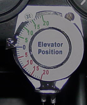 When raising and lowering the thrust line, I noticed, what I thought were, differences in stick position at cruise. But because it takes some time in-between flights to change the thrust line, I was not sure I could trust my impression of a difference. This has lead to an elevator position indicator shown to the left. Also, at some future time, I wish to investigate elevator position relative to flaperon settings for 50 mphi descents and for reflexing the flaperons at speeds higher than the normal cruise speed. Elevator and flaperon indicators will be necessary for these studies.
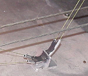
 A view of the stick elevator control horn assembly for an early FireFly (FF004). The spring maintains line tension. To zero out the scale one pulls up on the line that is attached to the spring with one hand. And with the other hand the scale is rotated or slipped toward the desired reading. Then spring tension is once again allowed to take over. A few tries and the scale can be adjusted. The string knots are each fixed with a drop of super glue.
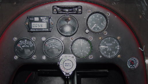 The latest look of the instrument panel.