|
|
|
|
|
|
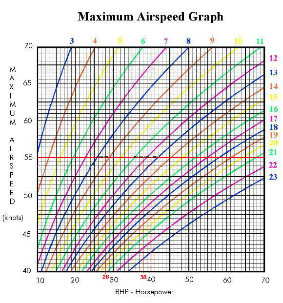
When I purchased the kit from Kolb Company Inc., I was assured that the FireFly could be built and flown as a legal ultralight. I have been flying to some flyins at which there were air shows, and I could have been ramp checked by FAA personnel. I got to checking and I found out that I am responsible for proving to the FAA that the FireFly is legal during a ramp check. If I can't and they want to be aggressive, it could cost $1,000. This encouraged me to put together a document that I could show to FAA personnel on the ramp to prove the FireFly is in compliance. The document is made up of AC 103-7 Appendix 1, 2, 3 & 4. The process is much like reverse engineering, in that one has to work backwards from two graphs, Maximum Airspeed Graph and Stall Speed, to determine the minimum drag factor required to keep a given engine from propelling you faster than 55 knots. And to determine the maximum wing loading for a given wing profile lift factor that will let the FireFly stall at less than 24 knots. There is an alternative to using the graphs, but it involves the taking of actual data during demonstration flights and a three person committee. This process would be almost impossible for me.
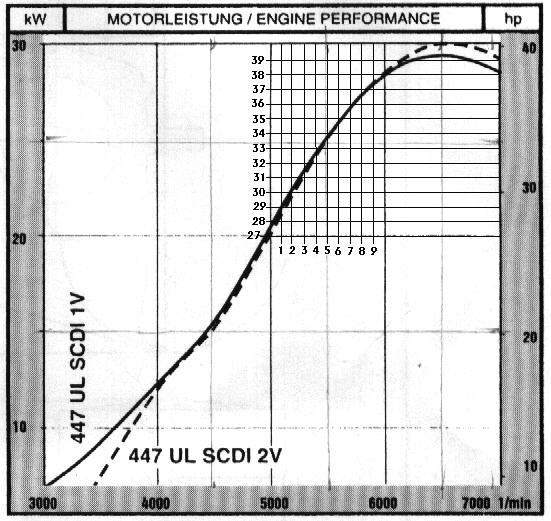
I was interested in three engine power settings 28, 38, and 40 horsepower. I consider the FireFly to be over powered and so I am interested in investigating how it will perform with less horsepower. Currently, I have my IVO propeller set to limit engine speed to 6,000 rpm and at this rpm the maximum horsepower the Rotax 447 can put out is 38 horsepower. Also I have found that if I set the engine at 4,600 rpm, the FireFly will cruise (gps) in the range of 55 to 60 mph. And so I selected 5,000 rpm as a maximum and picked 28 horsepower off the Rotax 447 power curve. These settings give the following total drag factors to limit the speed to 55 knots:
Then one proceeds to fill out the rest of Appendix 1 to see if the above total drag factors can be met. The print in bold is what I selected for the FireFly.
STEP ONE - Compute the total drag factor (See page 2 for further
breakdown of the values assigned to each category.)
1. Pilot Drag Factor (select one)..................................__3.50__
*Not Enclosed
-prone................................1.2
-supine...............................4.5
-seated upright.......................5.5
*Partially Enclosed
-lower half of body enclosed..........3.5
-only head exposed....................2.5
-streamlined, head behind windshield..2.0
*Totally Enclosed
-streamlined fuselage.................1.5
-boxy fuselage........................2.0
The above total drag factor indicates that I must continue to limit the Rotax 447 engine to 6,000 rpm to remain legal for maximum speed. If one has a FireFly with the 15 inch chord ailerons, the computations may come out a little better. Derating the engine to limit engine rpm by setting the pitch of a ground adjustable propeller is legal. AC 103-7, 20,c.,(1) c. Acceptable Methods of Determining the Maximum Level Flight
Airspeed of an Ultralight.
(1) A calculation, using the information in Appendix 1, is
an acceptable method for making this determination.
NOTE: The engine manufacturers maximum horsepower rating
will be used for all computations associated with maximum
level flight speeds (unless the operator can provide
documentation from the engine manufacturer that a method of
derating an engine will result in a predictable reduction
in horsepower)
AC 103-7, 20,d.,(1)&(2) d. Use of an Artificial Means to Limit the Maximum Level Flight Airspeed.
(1) An artificial means of restricting the total power output
of an engine in order to lower the maximum level flight
speed at full power would be acceptable if the method
used to restrict the power available is one which cannot be
modified, bypassed, or overridden in flight and the pilot or
operator can provide the FAA, on request, satisfactory evidence
that the vehicle meets the requirement of Section 103.1(e) (3).
(2) As a general guideline, a method is unacceptable if it can be
modified, bypassed, or overridden in any way while sitting in
the pilot seat so as to further increase the power. There may
be some ultralights which could be operated as ultralight
vehicles if such restrictions are employed to meet the
requirements of Section 103.1(e) (3). If you change or modify
the restricting elements, your vehicle may be ineligible for
use under Part 103.
AC 103-7, 20,e.
e.  Use of a Less Efficient Propeller/Shaft Arrangement.
    The use of a less efficient propeller/shaft arrangement to lower the
    maximum level flight speed at full power is acceptable, if the
    operator or pilot can provide the FAA, on request, satisfactory
    evidence that the vehicle meets the requirements of Section 103.1(e)
    (3).  If you change or modify that arrangement to increase the
    efficiency, your vehicle may be ineligible for use under Part 103.
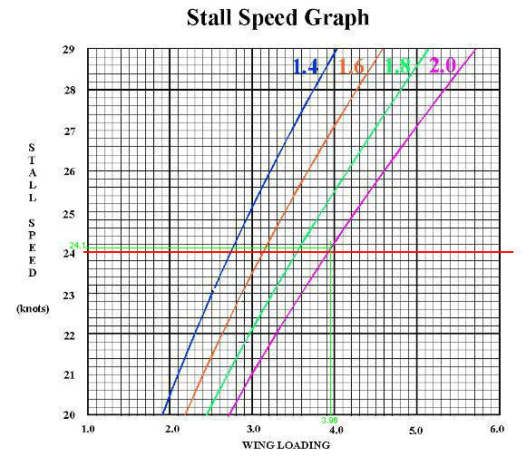
One can see that for a stall speed of 24 knots the maximum wing loading for a wing profile with lift factor of two is 3.90 pounds for square foot. But there is a little wiggle room in: AC 103-7, 21 21. MAXIMUM POWER-OFF STALL SPEED OF A POWERED ULTRALIGHT VEHICLE. The maximum power-off stall speed of an ultralight vehicle cannot exceed 24 knots (28 mph). Converting 28 mph to knots gives 28/1.15 = 24.3 knots. And so, may be I just squeek in with a calculated 24.1 knot stall speed. This condition is the most difficult to meet. The wing area is the wing chord times the wing span, and the load is determined by the ultralight empty weight plus the weight of the standard pilot (170 pounds) and the weight of five gallons of fuel. Because the FireFly is complete, one is not going to add wing area. I don't want to give up the brakes, strobes, some extra instruments, or trim for safety reasons. The only way to get more into compliance is to install a lighter engine and/or to reduce fuel tank capacity. The information contained in this appendix is intended to assist in a determination of an ultralight's ability to comply with Section 103.1(e) (2), a maximum power-off stall speed which does not exceed 24 knots. Computations made in accordance with the information provided may be accepted as satisfactory evidence of compliance. When using this information, no factors other than those provided here should be considered. (The values provided here are for relatively square, rectangular wings; they are not valid for noticeably swept or tapered wings.) Relevant considerations for this computation are:
STEP ONE - Add the weight factors.
Example: Empty weight 240 lbs.
Pilot weight 170 lbs.
Fuel weight 30 lbs.
440 lbs.
FireFly: Empty weight 247 lbs.
Pilot weight 170 lbs.
Fuel weight 30 lbs.
447 lbs.
STEP TWO - Divide the total weight by the total wing area to
obtain the wing loading of the vehicle.
Example: Weight = 440
Wing Area = 151 = 2.9 (Wing Loading)
FireFly Wing Area = Chord x Length = 5.13 x 22 = 112.9 ft2
FireFly: Weight = 447
Wing Area = 113 = 3.96 (Wing Loading)
STEP THREE - Select, from the wing profiles provided below,
the lift factor which applies to the ultralight
in question.
LIFT FACTOR WING PROFILE
STEP FOUR - Determine the power-off stall speed of the ultralight
through the use of the chart below.
INSTRUCTIONS:
Relevant considerations for this computation are:
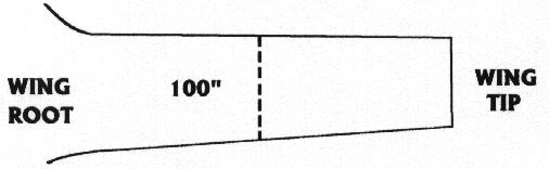
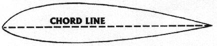
STEP ONE - Determine the mid-point of the wing and measure the mean chord line.
FireFly wing chord = 61.5" STEP TWO - At the mid-point of the wing, determine the chord line horizontal position on the airfoil profile (assuming straight line from the extreme forward point on the leading edge to the extreme rearward point of the trailing edge).
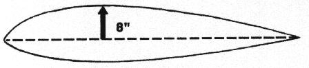
STEP THREE - Measure the distance from the chord line to the highest point of camber on the upper surface.
Firefly measurement
STEP FOUR - Divide the measurement obtained in step one into the measurement obtained in step three.
Example: Upper surface camber = 8 inches
Mean chord line length = 100 inches = 8% camber
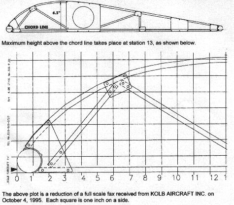
FireFly: Upper surface camber = 6.5 inches
Mean chord line length = 61.5 inches = 10.6% camber
Although I am marginal on the stall speed, I have put together a document, and I have asked an A & P Mechanic to sign and date it so that I have something to help me out if I ever get ramp checked. Also, I am getting a lighter engine ready to go. I should have it on by next Spring, and then I will rework the document to give me a better stall speed result. This was not an easy thing to do, and so I thought this html might help some other FireFly owners. If you would like a copy of the complete document made up of AC 103-7 Appendicies 1,2,3 & 4, and in Microsoft Word format (1,615 kb), click the mouse on download. |
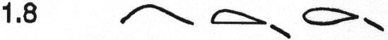 WING DESCRIPTION: Single surface with camber of 7 percent or
more or double surface with flaps extending up to 50 percent
of the total wingspan.
LIFT FACTOR
2.0
WING DESCRIPTION: Double surface with flaps extending more
than 50 percent of total wingspan.
This lift factor was picked for the Firefly. The FireFly has a
high camber wing with flaperons that extend over more than 50
percent of the wing.
WING DESCRIPTION: Single surface with camber of 7 percent or
more or double surface with flaps extending up to 50 percent
of the total wingspan.
LIFT FACTOR
2.0
WING DESCRIPTION: Double surface with flaps extending more
than 50 percent of total wingspan.
This lift factor was picked for the Firefly. The FireFly has a
high camber wing with flaperons that extend over more than 50
percent of the wing.