Dynamic And Static Air Speed Probes & ASI Tuning
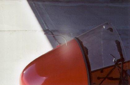 At first I placed a dynamic probe up on the top of the nose cone so that I or others would not walk into it. Also this placement saves weight. At this time there was no static port except under the nose cone. My air speed indicator indicated five to ten miles slow. For cross countries, I used a gps for true air speed.
|
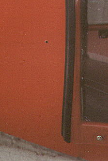 I noticed that as I pushed the throttle in and flew faster at a certain point the air speed indicator became static. This is because to maintain constant altitude one has to lower the nose. This exposes more of the pilot's body to the air flow and so one begins to push a static air bubble into the nose cone. And so the faster you are traveling the greater static air pressure under the nose cone and the greater the air speed indicator error. I added static ports on each side of the nose cone.
The position, 7-1/2 inches above the upper longeron and 2-1/2 inches in front of the instrument panel, was selected to keep the tubing length short and so the tubing would not interfere with one's feet on the rudder pedals. I purchased some black right angle barb fittings from the local auto supplier. I cut off one barb and glued over the non-barb end an aluminum washer made from aluminum house flashing. This washer gives a surface to glue to the inside of the nose cone. The holes were drilled in the nose cone to fit the outside diameter of the cut off tube protruding from the aluminum washer and the tube height is trimmed so that it will be flush with the outside nose cone surface. A little JB Weld was used to glue the assembly to the inside of the nose cone. The barb end was positioned so that it was up and toward the front of the nose cone. This helps to keep the tubing away from your feet. Then the air speed and rate of climb indicators were plumbed to the static ports. I have not had a chance to determine how accurate the system is, but I have read higher air speeds than ever before.
|
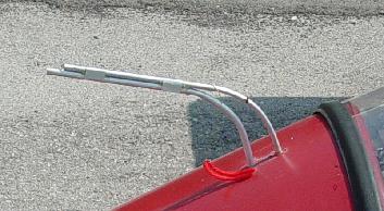 After I installed a new windshield that came up a little higher in the middle, my air speed indicator fell back to greater error as before. I added a static port by laying a tube on top of the dynamic tube. The end of the static port tube is plugged with epoxy, and three small holes were drilled through the circumference of the tube next to the plugged end. A hole was drilled in the nose cone centered and to the rear of the dynamic port tube pass through hole. The new static port tube was bent to pass through the hole and to lay on top of the dynamic port tube. Epoxy and two clips made from thin aluminum were used to fix the static to the dynamic port tube and epoxy a round the hole through the nose cone. I thought this change would surely improve the air speed indicator accuracy, but it did not.
|
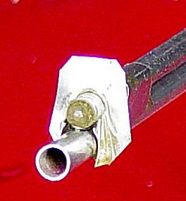 The only way to raise the indicated air speed is to increase the pressure differential across the static and dynamic ports. In an attempt to do this I cut and folded a small dam out of thin aluminum. I epoxied it just a head of the static air holes. This dam causes a local increase in the air speed as it passes by the static port holes and causes a reduction in the air pressure as seen by the holes. I was lucky and my first guess brought the indicated airspeed reasonably close the average of up and down wind gps speed readings. If the indicated airspeed became too high, I could snip or file away part of the dam to reduce the pressure differential.
|
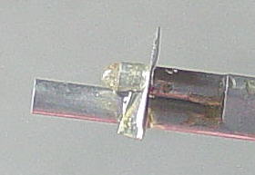 This gives a better view of the dam relative to the static pressure port holes. If one's airspeed indicator reads too fast, the dam should be placed behind the static port holes to slow the air and to decrease the pressure differential. The dam can be trimmed until the indicated airspeed error reaches a reasonable amount. If your static port probe is independently mounted, this same technique can be used to improve your indicated air speed readings.
|
 At first I placed a dynamic probe up on the top of the nose cone so that I or others would not walk into it. Also this placement saves weight. At this time there was no static port except under the nose cone. My air speed indicator indicated five to ten miles slow. For cross countries, I used a gps for true air speed.
 I noticed that as I pushed the throttle in and flew faster at a certain point the air speed indicator became static. This is because to maintain constant altitude one has to lower the nose. This exposes more of the pilot's body to the air flow and so one begins to push a static air bubble into the nose cone. And so the faster you are traveling the greater static air pressure under the nose cone and the greater the air speed indicator error. I added static ports on each side of the nose cone.
 After I installed a new windshield that came up a little higher in the middle, my air speed indicator fell back to greater error as before. I added a static port by laying a tube on top of the dynamic tube. The end of the static port tube is plugged with epoxy, and three small holes were drilled through the circumference of the tube next to the plugged end. A hole was drilled in the nose cone centered and to the rear of the dynamic port tube pass through hole. The new static port tube was bent to pass through the hole and to lay on top of the dynamic port tube. Epoxy and two clips made from thin aluminum were used to fix the static to the dynamic port tube and epoxy a round the hole through the nose cone. I thought this change would surely improve the air speed indicator accuracy, but it did not.
 The only way to raise the indicated air speed is to increase the pressure differential across the static and dynamic ports. In an attempt to do this I cut and folded a small dam out of thin aluminum. I epoxied it just a head of the static air holes. This dam causes a local increase in the air speed as it passes by the static port holes and causes a reduction in the air pressure as seen by the holes. I was lucky and my first guess brought the indicated airspeed reasonably close the average of up and down wind gps speed readings. If the indicated airspeed became too high, I could snip or file away part of the dam to reduce the pressure differential.
 This gives a better view of the dam relative to the static pressure port holes. If one's airspeed indicator reads too fast, the dam should be placed behind the static port holes to slow the air and to decrease the pressure differential. The dam can be trimmed until the indicated airspeed error reaches a reasonable amount. If your static port probe is independently mounted, this same technique can be used to improve your indicated air speed readings.