|
|
|
|
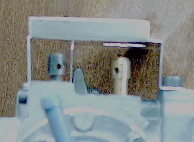 The roll pins were punched from the needle adjustment screws. A base plate was fabricated from 0.020 inch thick aluminum sheet and attached to the carburetor. Slightly oversized holes were drilled through the mounting plate for the outer bearing surface tubes.
|
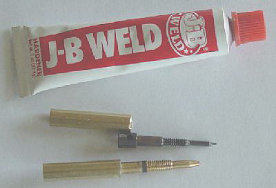 The exposed needle end OD's were 0.250 inches, so thin wall brass tubing was slipped over the ends and fixed into place with JB Weld. As the JB Weld was setting up, the tubes were rolled on a level surface to check tat the needle point was centered. If not it was adjusted until they rolled true.
|
 At this point the needle screws were re-installed through the base plate holes into their respective positions. Bearing surface tubes or sleeves were cut from 9/32 inch ID brass tubing and slid over the needle screw extensions, so that, the far end passed just through the hole in the base plate by about 1/4 of an inch. JB Weld was dabbed on the carburetor side of the base plate and around the bearing sleeves. Since the holes through the base plate were over sized this let the sleeve float into the correct position. As the JB Weld set, the needles were rotated back and forth to make certain the bearing sleeve set into the true position.
|
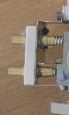
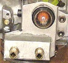 To finish up the bearing assembly, a three sided box was made from 0.020 thick aluminum sheet with two holes that locate it on the outer bearing sleeve surfaces. JB Weld was used to seal around the sleeves and the edges of the box. Then a second pour of JB Weld was made to completely fill the box.
To enable needle adjustment, a piece of 3/16 inch square brass tubing was slid inside the 0.250 inch ID needle jet extension sleeve and held in place with JB Weld. To get it to slide in, one must file a little material from the corners. |