|
|
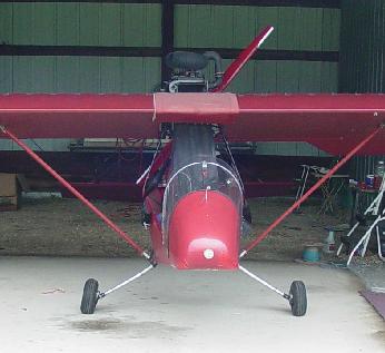 I like to make three point landings, but at Marion, Indiana, my attention became diverted and I "plopped" the FireFly. After the landing, I was congratulating my self on getting out a bad situation when I noticed that the FireFly landing gear was partially retracted. Although camber was negative, other wheel alignment was good and I was able to taxi, enjoy the fly-in, and later fly back to I22 without any additional problems.
After thinking about it, I could not remember the FireFly striking the asphalt that hard. I have a full sling seat that is not attached to the rear cross member. I thought that may be this was the reason I did not feel much impact. During a previous landing out in a corn stalk field, the left wheel ran between two rows, but the right wheel ran down a row. I remember feeling the hammering of the right wheel and the right landing gear leg was bent. I thought that the bent leg was caused by the hammering. And then I remembered that although that leg was bent, the FireFly trailed true while being pulled behind a pickup back to the airport. All three of these legs were bent in the plane made up of the legs and the fuselage sockets. So in the corn field, it was not the hammering, but too much dropping force (plopping) on the right leg.
|
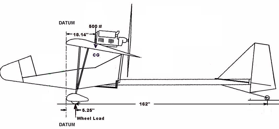 To find the gross weight one G force on the main wheels, I used the a CG distance of 18.14 inches and summed the moments about the tail wheel.
Therefore: Wheel Load = 500# x (162" + 5.25" - 18.14") / 162" = 460# But what is of interest here is not the load carried by the wheels, but by each leg. So the Wheel Load was divided by two and five pounds was subtracted for the combined weight of one wheel, axle, and brake. So, at one G, each leg must support a vertical load of 225 pounds. |
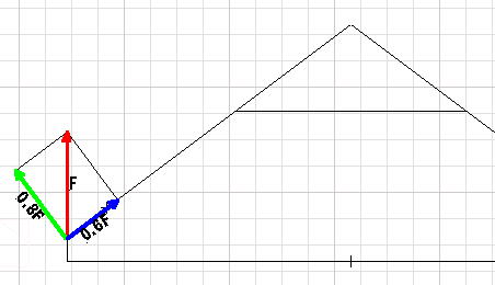 Vector algebra lets one resolve the 225 pound force into components perpendicular to and along the leg center line. The perpendicular component (green) is the one that produces the leg bending. For one G, this component is 0.8 x 225# = 180 pounds.
|
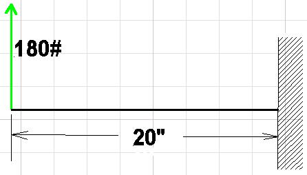 Rotating and cutting away the cage, this looks like a typical cantilever beam problem. The maximum bending moment will be at the wall or at the end of the leg socket. Once the bending moment has been found, one can calculate the corresponding stress at the end of the socket or at the wall. The maximum bending moment is 20" x 180# = 3,600 inch - pounds.
For a round rod the equation for maximum stress is as follows: Max Stress = 4M/(pi x r x r x r) (Don't know how to get a cube power)
Where: The maximum one G leg stress at the bottom of the socket is 25,754 psi. If one divides the published yield stress for 2024 aluminum 47,000 psi by 25,754 it says that the gear leg will start to bend at 1.825 G's. This is lower than it should be because no allowance was made for tire friction to take some side load as the leg flexes out. The dry pavement coefficient of friction is 0.62, and for wet pavement it is 0.36. So one can calculate a range of more realistic values. |
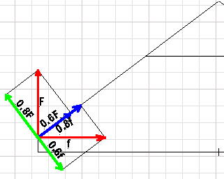 The friction force (f) is defined as the normal force times the coefficient of friction. In this case the normal force is tbe weight the tire exerts on the ground. From before, it was found that both wheels had to support a one G load of 460#, and so the normal force will be 460#/2 or 230#. Starting with the rubber tire on a dry surface, the friction force will be 0.62 x 230# = 143#. The component perpendicular to the leg center line is 0.6f or 0.6 x 143# = 86#.
|
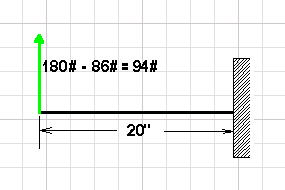 One can see that the resultant force has been reduced by almost half. Upon recalculating the maximum bending stress is 13,735 psi. So on dry pavement the leg will sustain a 3.42 G landing before yielding.
So the gear leg will sustain landings of 1.825G to 3.42G depending on the variation in surface conditions from wet ice to dry pavement. It is even worse than it appears in that when the frictional force is exceeded and the wheel starts to slip sideways all bets are off. Dynamic coefficients come into play and they are much lower than static coefficients. All of this indicates that, one must be very gentle with the FireFly while landing. If not, you have to straighten legs or purchase new legs. Both options keep you from flying. One does not want to depend on frictional forces to help support the leg. As shown below, one way to replace the unreliable frictional force is to run a cable from the axle bolt on the lower leg to the upper leg attachment bolt of the opposite leg or to the top of the opposite leg (red). |
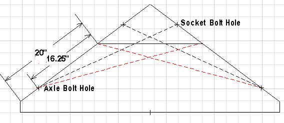
Although the cable (red) to the top of the opposite leg will give the most support, I decided to check out the cable that crosses to the opposite leg attachment bolt. The cable is shorter and there is less drag due to the cable being exposed to the passing air. If the cables are attached to the back side of the socket and axle, they will not interfere with anything and one does not have to put hole through the fabric. One-eighth inch diameter cable will support up to 2,000 pound before breaking. |
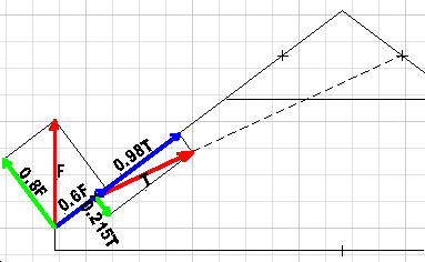
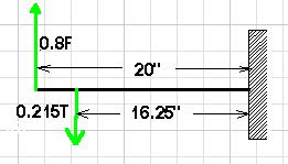
Things are getting a little more complex because the bending forces have been applied at two separate points. What is of interest is how much effect does a tension (T) of 2,000# have on the maximum force (F) required to bend the leg. |
If one solves the previous bending stress formula for the leg bending moment at the socket while using the yield strength, it will give the maximum moment that will not bend the leg. M = (47,000 x pi x r x r x r)/4 Or M = 6,570 in-pounds
Summing the moments at the wall or socket gives:
M = 0.8 x F x 20 - 0.215 x T x 16.25 But T = 2000# Therefore M = 16 x F - 6770 = 6570 in-pounds Solving the last part for force F gives: F = (6570 + 6770)/16 = 834 pounds. This is the maximum wheel load that will not bend the leg or break the cable. if one G load was 225 pounds, then 834/225 = 3.93G is the new landing gear max load. This is a 100 x (3.93 - 1.825)/1.825 = 115% improvement over the wet ice frictionless equivalent and it is a 100 x (3.93 - 3.42)/3.42 = 15% improvement over dry pavement. Running the cable from the axle bolt to the socket bottom on the opposite leg will let the maximum wheel force rise to 1,170 pounds and the maximum G load rise to 5.2G. It is amazing what a short piece of 1/8th inch diameter cable can do. These G numbers are a little on the high side because the compressive forces lying along the leg axis have been ignored. Now I have to get busy and install them. |
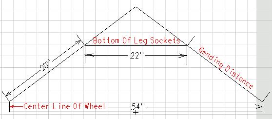 After straightening the legs, I took some measurements so that I could check out landing leg strength. I assumed the major bend is going to take place at the bottom of the leg socket. Also, I assumed each leg will take half of the total load or equal load. The force application point will be straight up through the center of the wheel. By extrapolating the leg center line on down through the wheel vertical center line, I found the maximum bending moment arm length to be 20 inches. For the analysis, I am assuming that the legs and sockets lie in a vertical plane, and the FireFly is at gross weight.